

Best Tool Grinding Machine Company Traits That Drive Superior Accuracy
2026-11-17
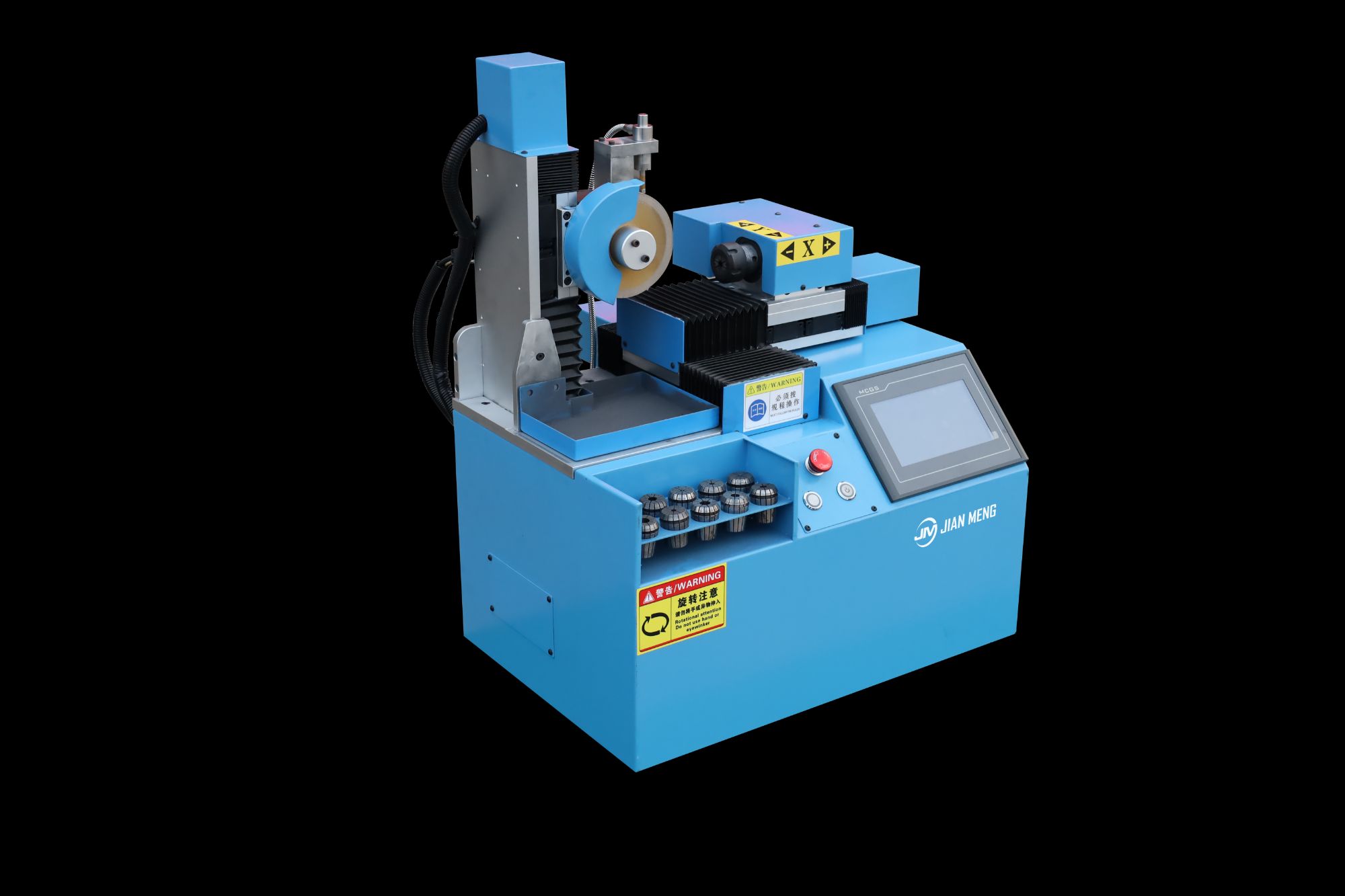
Ask any shop owner what separates a forgettable tool grinder from one that holds micron-level accuracy for years, and the answer rarely stops at spindle power. It usually comes back to the habits of the company behind the machine—how they test, what they refuse to compromise, and where they source critical components. That is the lens we use here, with JIAN MENG serving as a useful reference point among builders known for accuracy that outlasts the warranty.
Why Tool Steel Selection Sets the Accuracy Ceiling Before Grinding Begins
A grinder can only refine what the steel allows. If the substrate moves unpredictably under wheel pressure or releases internal stress unevenly during stock removal, the final few microns become a lottery no matter how precise the machine is. Tool steel with a coarse carbide structure or inconsistent through-hardening tends to pull dimensions out of tolerance long after the part leaves the chuck.
Powder metallurgy grades often establish a quieter baseline because their carbides are finer and more evenly distributed. That translates into less edge chipping, more stable passes, and fewer surprises when measuring between centers. Conventional ingot-cast D2 can still hold tight geometry, but it asks for slower feeds and sharper wheels to stay inside that narrow window.
The accuracy ceiling is largely set before the first abrasive grain touches the surface. Choosing a steel with predictable distortion behavior and uniform hardness gives the grinding process a realistic target. Without that, operators end up chasing thermal drift and residual stress instead of simply removing stock.
What Thermal Drift Actually Does to a Cutting Edge Over an Eight-Hour Shift
By hour three, the edge isn't where you left it. A tool that measured 20.003 mm at the spindle nose after morning warm-up can easily walk six or eight microns by mid-shift, not because the machine is broken, but because spindle growth, ballscrew expansion, and casting heat all settle into a new equilibrium. The real problem is that the shift rarely waits for that equilibrium. Operators chase offsets, scrap a few borderline parts, then chase them again when the shop warms past the afternoon sun through the skylights.
What gets overlooked is how uneven that drift really is. The X-axis may move one direction while the Z grows another, and the column itself tilts a few arcseconds as one side takes heat from the motor and the other side stays cooler near the chip pan. So you're not fighting a single number you can type into a wear offset. You're fighting a slowly bending coordinate system that shifts as the coolant tank warms, as the spindle brake cycles, as the operator opens and closes the bay door. A cut that was dead center at 9 a.m. can be a tenth and a half high at 2 p.m., and nobody's morning offset table knows why.
Some shops try to fix this with longer warm-up routines, but running the spindle at 8,000 rpm in fresh air for twenty minutes doesn't recreate the real thermal load of a heavy roughing cut. Others keep a logbook of position readings, though most of those logs quietly disappear after a couple of weeks because the numbers don't repeat day to day. The honest answer is that thermal drift is less a setting to correct and more a behavior to manage: shorter toolpaths, periodic re-referencing, cutting the most critical features during the flattest part of the shift, or simply accepting that a machine's midnight geometry isn't the same as its noon geometry.
How Spindle Runout Quietly Erases Microns and How Bearing Choices Bring Them Back
Runout rarely announces itself with a bang. It lives in the space between a perfect circle and the path a tool actually traces, often measured in microns that accumulate into scrapped parts before anyone thinks to check the spindle. A few microns at the taper, another handful at the tool holder, a touch of imbalance from the drawbar — and suddenly your surface finish has a fingerprint no amount of feed tuning can remove. The real cost shows up later, in dimensional drift that shifts with every tool change and in bearing races that wear unevenly because the load never sits where the design assumed it would.
Bearing selection pulls runout back from the edge, but not in the way a tighter tolerance solves everything. The difference comes down to how rolling elements share the load when the shaft deflects a micron or two. A high-precision angular contact pair with controlled preload doesn’t just spin smoother; it resists the tiny orbital wander that turns one bad pass into a repeating pattern. Ceramic balls help here too — not for the marketing bullet point, but because lower mass and higher stiffness mean the spindle settles back into its intended axis faster after every cutting impulse.
The quiet fix is usually a matter of matching bearing stiffness to the actual error mode. If runout stems from a slightly bell-mouthed taper, a stiffer front bearing arrangement can mask the symptom without fixing the cause. If it comes from thermal growth, choosing a bearing with a more predictable internal clearance curve does more than grinding the taper again. Either way, the microns come back when the spindle stops fighting itself and starts distributing load the way the bearing’s geometry intended.
When In-Process Measurement Catches Drift Before It Reaches the Finished Edge
A spindle load creeps upward on the third pass while the cutter is still two stations away from the final edge profile. That small change never shows up in the dimensional report because the part has not reached the measurement bench yet. When the process monitoring system flags the trend, the operator adjusts the tool offset before the edge geometry wanders outside tolerance. The finished edge never sees the problem.
This is the real advantage of checking parameters in process rather than waiting for a post-process CMM run. In many shops, drift starts as a barely visible shift in torque, vibration signature, or coolant temperature. By the time a finished edge dimension is out of spec, several parts have already carried the same error downstream. In-process measurement shortens that feedback loop to minutes instead of batches.
The result is not just fewer scrap parts. It also removes the temptation to compensate for unstable processes with extra grinding or hand finishing at the edge. The process itself becomes the control point, so the finished edge reflects what was held steady upstream rather than what was rescued at the end.
Who Keeps Calibration Honest When Tight Tolerances Are On the Line
In a shop where a few microns decide whether a part ships or gets scrapped, the first line of honesty is usually the person standing at the machine. A machinist who sees the same bore gage read differently after lunch will start asking questions long before any auditor shows up. They may not sign the calibration sticker, but they notice drift because they pay for it in rework and rejected lots.
The formal side sits with the metrology lab or an outside service that keeps its reference standards traceable and its environment controlled. Yet the real test is not the certificate on the wall. It is whether the tech is willing to say a gage should not pass because the lab temperature swung, or because the anvils show uneven wear. Honest calibration sometimes means refusing to put a number on a tool until the conditions make that number trustworthy.
Behind them are quieter roles: the person logging humidity shifts, the quality engineer who shortens calibration intervals after a bad run of measurements, the toolroom lead who pulls a batch of micrometers because one failed. Tight tolerances stay honest only when that whole chain treats drift as something to catch, not something to explain away later.
Where Clean Power and Floor Stability Show Up in Ground Tool Accuracy
A grinder's accuracy tends to get blamed on tooling, but voltage drop on a long extension cord can create the same scratches and swirls that people chase with new diamonds. When the motor speed moves around under load, the head doesn't keep a consistent bite. Clean, steady power lets the drum speed stay where the operator set it, so the pattern left behind is repeatable from one wall to the next.
Floor stability shows up in the edges and overlaps. On a slab that bounces or has a loose section, the machine leans just enough during each turn that the cut depth changes without any adjustment at the controls. The operator compensates, then overcompensates, and the floor ends up with shallow waves that read as inaccuracy in the tool. A stable substrate gives the machine a fixed reference plane; without that, even a freshly calibrated unit will look sloppy.
When both conditions are right, the difference is not dramatic moment by moment. It accumulates over a thousand square feet as less rework, fewer touch-up passes, and a finish that holds the same tolerance at the door as it does at the far column line.
FAQ
Precision usually comes down to how they handle thermal stability, spindle design, and in-house validation. Top builders run extended cutting trials on actual tool geometries and publish the measured runout and surface finish data instead of relying on brochure figures.
It often traces back to structural rigidity and temperature control. Machines with hand-scraped guideways, symmetric frames, and active cooling loops hold geometry longer. The best companies also audit machine capability after installation rather than only during pre-delivery.
Honest application engineering, custom workholding, and wheel dressing routines tailored to the carbide grade. A company that asks for your exact blank tolerances and coolant chemistry before quoting is usually the one that can hold radius repeatability run after run.
It is decisive once the mechanical base is solid. Look for direct-drive rotary axes, high-resolution encoders, and conversational programming that does not hide compensation settings. Companies that allow manual override of wheel wear compensation tend to produce better long-term results.
Demand a capability study on your actual workpieces or drawings. Strong companies offer a documented runoff with multiple tool changes, thermal cycling, and measurement on a calibrated CMM or tool inspection machine before shipment and again after installation.
Yes. Check whether they provide local metrology support, spare spindle lead times, and on-site calibration guidance. The best firms treat post-installation drift as a technical problem to solve, not as a warranty dispute to avoid.
Minimal overhang, short force loops, and fewer stacked axes. Companies that prioritize a compact grinding zone with direct feedback scales on every linear axis typically outperform designs that chase large travels or multi-tasking features at the expense of stiffness.
Conclusion
Accuracy in tool grinding is rarely the result of one dramatic upgrade. It is set long before the wheel touches the blank, beginning with the choice of tool steel and the way its hardness, grain structure, and carbide distribution respond to abrasive cutting. From there, the machine earns its tolerance every shift. A spindle with minimal runout and bearings chosen for stiffness rather than convenience keeps micron-level material removal predictable, while thermal drift quietly changes clearance angles and edge position as the day wears on. Shops that hold tight edges treat temperature as a process variable, not a background condition. They watch coolant temperature, warm-up cycles, and ambient swings because an eight-hour shift can shift geometry even when the operator does nothing wrong.
The most credible grinding machine builders also design for verification and stability. In-process measurement acts as a live checkpoint, catching drift before it reaches the finished edge instead of discovering it in final inspection. Calibration stays meaningful only when it is tied to reference standards, documented, and repeated against known artifacts rather than left to an annual service call. Even the best gauging cannot fix a machine sitting on a weak floor with dirty or unstable power. Clean electrical supply and a stable foundation may not appear on a spec sheet headline, but they show up directly in ground tool accuracy. The companies worth trusting are the ones that treat these details as core engineering, not afterthoughts.
Contact Us
Contact Person: Jeanie
Email: [email protected]
Tel/WhatsApp: +86 19805122954
Website: https://www.jianmeng.com